
Secondary fault current is one of those numbers nobody thinks about until a breaker welds itself shut. On a small step down transformer it is easy to wave off, because the box is the size of a shoebox and the whole thing sells for less than a good drill. Then you read the plate. A 2000VA single phase unit at 4.5% impedance will push about 404 A into a dead short across its 110V winding, which is 22 times the current it is rated to carry all day long. That is enough to arc, enough to cook a 1.5mm² cable in a couple of seconds, and enough to finish a cheap breaker in one event.
This page does the arithmetic for you. Put in the rated capacity, the secondary voltage and the impedance printed on the nameplate, add the X/R ratio if the plate or the datasheet gives it, and you get full load current, the impedance in ohms split into resistance and reactance, the prospective fault current, the fault level in kVA, and the asymmetric first peak. The peak follows the IEC 60909 method. It is the same sequence we run here in Yueqing when a customer mails a single line drawing and asks whether the breakers already on his panel are still good.
If you only have thirty seconds: divide full load current by the impedance as a decimal. A 4% transformer multiplies its own rated current by 25. Everything below is detail stacked on top of that ratio.
What transformer impedance actually tells you
Impedance voltage is a test result, not a design opinion. You short the secondary, raise the primary voltage until rated current circulates, and read what percentage of rated primary voltage it took to get there. That single figure carries two pieces of news at once.
The first is regulation. A transformer with higher impedance loses more voltage between no load and full load, because the same current flowing through a larger series impedance drops more volts. Push a 6% unit to its rating and you will see the secondary sag further than a 4% unit of the same size.
The second is fault limitation, and it is the one that keeps people safe. All the current that a short circuit wants to draw has to pass through that series impedance, so the impedance is effectively the only brake in the circuit. Bigger impedance, smaller fault current. Smaller impedance, more violent fault.
On the dry type units we build, that ohmic impedance is mostly leakage reactance. The primary and secondary windings sit a few millimetres apart, the flux that leaks across that gap does not link both windings, and the effect behaves like a reactor in series. Copper resistance is the smaller share on anything above a couple of kVA, which is why the X/R ratio climbs as transformers get bigger.
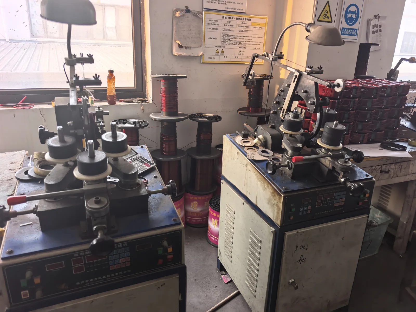
Find the impedance number on the plate before you type anything
On our nameplates it appears as Uk, %Z, or the words impedance voltage, usually with a percentage next to it. European plates sometimes print uk and German ones spell out Kurzschlussspannung. Spanish and Latin American plates often say impedancia. They all mean the same measurement.
Two traps are worth naming. First, some plates give the short circuit voltage in volts instead of a percentage. Divide that by the rated winding voltage and multiply by 100 and you have your percentage. Second, do not borrow the value from a transformer you assume is similar. Core material, winding interleaving, whether the unit has an electrostatic shield, and even how tightly the coil is wound all move the leakage reactance around, and two 3 kVA units from different factories can easily land at 3.8% and 5.2%.
If the plate is worn smooth or the unit is old and undocumented, use a typical value from the table below and treat the answer as an estimate rather than a design basis. Our guide to reading a transformer nameplate walks through every field, including the ones that are usually ignored.
The three steps behind the calculator
The order matters, so here it is in the sequence the script runs it.
- Full load current. Single phase is
If = S / V. Three phase isIf = S / (1.732 x V), with V as the line to line voltage. Use the winding the fault happens on. On a 220 to 110V unit, the 110V side is the one that matters, and feeding 220 into the formula halves your answer in the wrong direction. - Impedance in ohms. Base impedance is
Zb = V² / S, then|Z| = Zb x %Z / 100. To split it,R = |Z| / √(1 + (X/R)²)andX = R x X/R. Without the split you still get fault current, but you cannot get the peak. - Fault current and peak.
Ik = If x 100 / %Zfor a bolted fault at the terminals. Fault level isSk = S x 100 / %Z. The peak isIp = κ x √2 x Ik, withκ = 1.02 + 0.98 x e-3/(X/R).
Notice that the impedance value cancels almost everything else out of step three. Fault current is just full load current scaled by the inverse of the per unit impedance. That is why a 630 kVA distribution transformer at 6% throws about 15 kA while our 2 kVA bench unit at 4.5% throws 404 A.
A worked example you can check by hand
Take a 2000VA single phase step down transformer, 230V in, 110V out, nameplate impedance 4.5%, X/R around 2.5. Punch it into the calculator and these are the figures you should see.
| Step | Working | Result |
|---|---|---|
| Full load current | 2000 / 110 | 18.18 A |
| Base impedance | 110² / 2000 | 6.05 Ω |
| Impedance at 4.5% | 6.05 x 0.045 | 0.272 Ω |
| Resistance | 0.272 / √(1 + 2.5²) | 0.101 Ω |
| Reactance | 0.101 x 2.5 | 0.253 Ω |
| Fault current | 18.18 / 0.045 | 404 A |
| Fault level | 2 kVA x 100 / 4.5 | 44.4 kVA |
| Peak factor κ | 1.02 + 0.98 x e-1.2 | 1.315 |
| Asymmetric peak | 1.315 x 1.414 x 404 | 751 A |
Read the last line carefully. The RMS current a breaker has to interrupt is 404 A, but the current it has to close onto, and survive for the first half cycle, is closer to 751 A. That gap is roughly 1.86 times, and it is the reason a device rated only on thermal current can fail on a transformer branch without ever being overloaded in the ordinary sense.
Typical impedance values, and why two transformers of the same size differ
Use these bands to sanity check a plate or to fill a gap when the plate is unreadable. They are drawn from standard dry type practice and from what we see on incoming units for repair.
| Capacity | Typical %Z | Typical X/R | What it means in practice |
|---|---|---|---|
| 0.05 to 1 kVA | 2% to 4% | 1.2 to 2.5 | Copper dominates, fault current is roughly 25 to 50 times rating |
| 1 to 5 kVA | 3% to 5% | 2 to 3.5 | Most bench and appliance transformers land here |
| 5 to 25 kVA | 3.5% to 5.5% | 3 to 5 | Common for workshop machine feeds |
| 25 to 100 kVA | 4% to 5.5% | 4 to 7 | Peak factor starts to bite on breaker selection |
| 100 to 630 kVA | 4% to 6% | 6 to 15 | Distribution standard, paralleling usually forces equal %Z |
| 630 kVA to 2.5 MVA | 6% to 8% | 15 to 30 | Specified high to protect downstream switchgear |
| Above 2.5 MVA | 8% to 14% | 30 to 60 | Fault level is the binding constraint, not regulation |
Two units of the same rating can still carry different percentages because the number is a by-product of how they are built. More turns of thinner wire raises resistance. A bigger window between windings raises reactance. Interleaved windings, where the secondary is sandwiched inside the primary, cut leakage reactance and drop the percentage noticeably, which is one reason audio and laboratory transformers often measure lower than industrial units of the same size. IEC 60076-5 lists preferred values so that units can be paralleled, and if you plan to run two transformers in parallel the percentages have to match within about 10%, otherwise the one with lower impedance takes more than its share of the load.

Turning the fault current into a breaker decision
Fault current on its own is not a verdict. It only becomes one when you compare it with the ratings printed on the protective device.
The first comparison is breaking capacity. The device’s Icu, and preferably its Ics as well, has to be at least the prospective fault current at the point where it is installed. A 6 kA MCB on a 404 A branch has enormous margin. The same MCB on the secondary of a 630 kVA transformer with 15 kA available is not a protective device, it is a fire risk.
The second comparison is the magnetic trip threshold. A B curve breaker trips instantly somewhere between three and five times its rating, a C curve between five and ten, a D curve between ten and twenty. If your fault current divided by the breaker rating lands below that band, the breaker will not trip instantly on a dead short and you are relying on the thermal element, which is far too slow. With 404 A available and a 20 A C curve breaker, you are at 20 times, so instantaneous trip is comfortable.
The third comparison is the one people forget. Transformer inrush at switch-on can reach eight to twelve times rated current for a few cycles, and a breaker picked purely to be sensitive to fault current may nuisance trip every time the unit is energised. That is why a slightly slower curve, or a short delay, often suits transformer primaries better. Our notes on transformer inrush current and on protection devices for small transformers cover the selection side in more depth than a calculator can.
One more thing worth saying plainly: the fault current at the load end of a long cable is not the fault current at the transformer terminals. Cable impedance eats into it, sometimes by half on runs over thirty metres. If the run is long, size the breaker on the value at the device, not at the transformer. The voltage drop and cable sizing guide has the working for that.
Why the peak matters as much as the RMS value
A short circuit almost never begins at the instant the voltage waveform crosses zero. If it strikes close to a peak, the current starts with a DC offset riding on top of the AC component, and that offset decays over a few cycles as the circuit’s own resistance absorbs it. The result is a first half cycle that overshoots well above the steady RMS value.
IEC 60909 ties the overshoot to X/R through the factor kappa. Low X/R means a resistive circuit where the offset dies quickly and kappa stays near 1.02. High X/R means a reactive circuit that holds the offset long enough for a serious peak, and kappa climbs toward 2.
| X/R ratio | κ | Peak as a multiple of RMS |
|---|---|---|
| 1 | 1.07 | 1.51 x |
| 2.5 | 1.32 | 1.86 x |
| 5 | 1.56 | 2.20 x |
| 10 | 1.75 | 2.47 x |
| 20 | 1.87 | 2.64 x |
| 50 | 1.95 | 2.75 x |
Making capacity, busbar supports, terminal blocks and the bracing inside a panel are all sized on that peak, not on the RMS figure. When we quote a small transformer into a market where the panel builder is used to oversized switchgear, this is usually the number that ends the argument.
If the plate and datasheet both stay silent about X/R, the calculator falls back to a capacity based default and tells you which one it used in the small line under the results. Treat a defaulted peak as an estimate with maybe ten percent of slack in either direction.
Where this result stops being the whole truth
The calculation assumes an infinite source behind the transformer, and for most of our customers that is fair. It stops being fair in a handful of situations, and it is better to know them than to be surprised later.
- Weak sources. A 2 kVA transformer fed from a 5 kVA generator is not fed from an infinite bus. The generator’s own impedance is comparable to the transformer’s, and the real fault current will be a good deal lower than the calculator says. Add the source impedance in series and rerun.
- Motor contribution. Running induction motors feed the fault for a few cycles. On a workshop with several machines online, add roughly four times the total motor kVA to the fault level.
- Arc faults. A bolted fault is the worst case and also the cleanest case. Real arcing faults have variable impedance and often draw less current, which is exactly why series arc detection exists.
- Temperature. Winding resistance rises with temperature. A transformer that has been at full load for six hours has slightly higher R and slightly lower fault current than a cold one at the same voltage.
- Impedance tolerance. Standards allow the declared figure to be off by around ten percent without the unit being out of specification. Your 4.5% may measure 4.95%, and 4.95% means a lower fault current than you planned for.
- Parallel units and cascades. Two transformers in parallel combine their per unit impedances, and a step up followed by a step down needs both handled as one network. Do not add percentages.
Mistakes we see in drawings and enquiries
- Using the three phase formula on a single phase unit. The 1.732 is not a rounding detail, it is a 73% error.
- Dividing by the percentage twice, once to get ohms and again to get current. Pick one route.
- Mixing kVA and VA in the same sheet, which quietly shifts every answer by a factor of a thousand.
- Taking impedance from the wrong column of a datasheet, typically one measured at a different reference temperature than the one the rest of the table uses.
- Applying the terminal fault current to a device thirty metres down the cable run, where the real value may be half of it.
- Assuming the nominal voltage. A 230V nominal supply sitting at 240V raises fault current by about 4%, and in markets where 240V is normal the plate may only say 230V.
What to do with the number once you have it
Four checks, in order, and then you can stop.
- Compare the fault current with the breaking capacity of every device between the transformer and the load. The weakest device sets the limit for the whole branch.
- Check that the fault current is high enough to trip the chosen curve instantly. If it is not, the device is decorative.
- Check the cable’s short circuit withstand for the clearing time of that device. Small cables on big transformers are the classic mismatch.
- Check the peak against making capacity and against the mechanical strength of whatever holds the conductors in place.
For the range we build, from 500VA bench units up to 10 kVA workshop transformers, secondary fault current at 110V or 220V typically lands between roughly 100 A and 600 A. Standard DIN rail breakers with 6 kA breaking capacity cover that comfortably, so on these sizes the decision is rarely about fault current at all. It is about inrush, about whether the breaker will hold when you switch the unit on, and about whether the transformer is big enough in the first place. If that last question is still open, the transformer sizing calculator starts from the appliance wattage instead of from a nameplate, and the guide on converting amps to VA for transformer sizing covers the arithmetic behind it. Our step up and down transformer range lists the models these numbers usually point to.

Frequently asked questions
How do I calculate transformer fault current from percent impedance?
Divide the full load current by the impedance expressed as a decimal. For a 2000VA single phase transformer with a 110V secondary and 4.5% impedance, full load current is 2000 / 110 = 18.2 A, and 18.2 / 0.045 = 404 A of prospective short circuit current. Three phase units use full load current = VA / (1.732 x line voltage) first, then the same division.
What is a typical impedance value for a low voltage transformer?
Most dry type low voltage transformers between 1 kVA and 100 kVA sit between 3% and 6%. Units under 1 kVA often land at 2% to 4% because the winding resistance is a large share of the total. Distribution transformers from 100 kVA to 630 kVA usually run 4% to 6%, and anything above 2.5 MVA is commonly specified at 8% or higher to keep fault current within switchgear ratings.
Does higher impedance mean lower fault current?
Yes, and that is usually why utilities and specifiers ask for it. Doubling the impedance halves the fault current. The cost is regulation: a 6% transformer sags more under full load than a 4% one, and it runs warmer for the same output. On small step down units, going above 6% to chase a lower fault current is rarely worth the voltage drop.
Can this calculator be used for three phase transformers?
Yes. Switch the supply system to three phase and the calculator puts the square root of three into the full load current and uses the line to line voltage for the base impedance. Enter the line to line secondary voltage, not the phase voltage. The fault current it returns is the three phase bolted fault value at the secondary terminals.
Why is the asymmetric peak higher than the RMS fault current?
A fault rarely starts at the exact moment the voltage waveform crosses zero. When it starts near a voltage peak, the current carries a decaying DC offset on top of the AC component, so the first half cycle overshoots. IEC 60909 expresses this with the factor kappa, which depends on the X/R ratio: peak = kappa x 1.414 x RMS. That peak is what breaker making capacity and busbar supports have to survive.
One last check before you quote a breaker
Impedance is a small number on a plate that decides a large number in a panel. Get the percentage, get the voltage of the winding the fault happens on, and the rest is division. If the answer you get looks implausible, the usual cause is a kVA and VA mix up or a plate read from the primary when the fault is on the secondary. Both take ten seconds to fix.
If you would rather have someone look over the whole picture, send the nameplate photo and the single line drawing. We answer within 24 hours, and if a different model in the range fits better, we will say so. Related reading that pairs well with this page: single phase versus three phase sizing, what size low voltage transformer you actually need, and the VA to watts converter if you are still working out the load side. For supply voltages in a specific country, the voltage by country reference saves a phone call.