Step Down Transformer for Elevators and Lifts: 220V to 110V
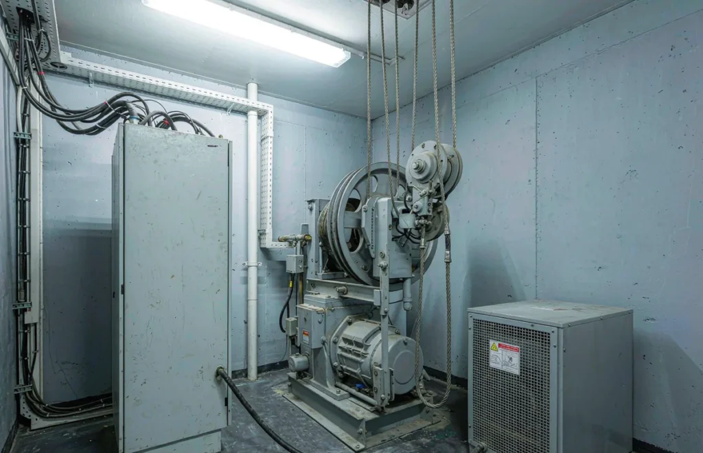
An elevator is the one machine in a building that a visitor will notice has failed within about four seconds. There is no quiet way to be stuck. That raises the stakes on the small transformer sitting in the machine room feeding the 110V control circuit, a box most people never see and few think about until a service technician is standing beside it at two in the morning.
I take enquiries for a step down transformer for elevator work from lift installers, maintenance companies and building contractors, and the pattern is always similar. The main drive wants a three-phase supply, the control cabinet and its accessories were built to American or Japanese standards and run on 110V, and the machine room has to feed both from the same incoming supply. Getting the control feed right is the part I want to talk through here, because it is where the avoidable mistakes live.
One distinction up front, since it saves time later. The transformer in this conversation is not feeding a motor that drives the car. It is feeding the control and safety side of the installation, plus the lighting and communications that go with it. That is a small load in watts, but it is the load that must never drop.
Why a Lift Control Circuit Runs on 110V
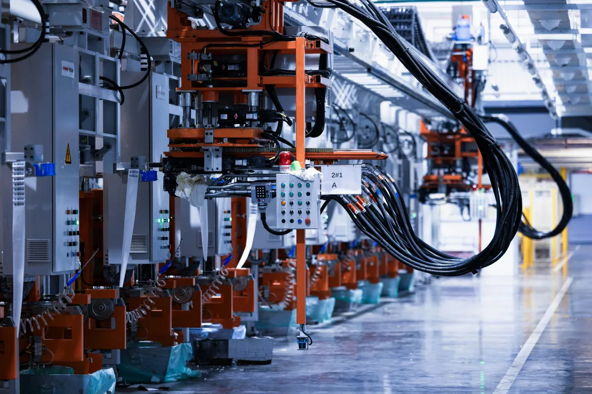
Most of the lift equipment that travels around the world comes out of factories where 110V is the working standard for control circuits. Controllers, relays, contactors, door operators and the sensors that watch the landing all get built to that voltage, and they arrive that way no matter where the building stands. The drive motor may be fed from 380V three-phase, but the brains of the installation expect something much smaller.
There is a good engineering reason behind that choice, and it is not only history. A control circuit running at a lower voltage is safer for the technician who has to work on it with the panel open, and the components are smaller and cheaper to replace. So the industry kept the control side at 110V even in countries where the mains sits at 220V or 230V, and the transformer in the cabinet is what bridges the two.
It also means the control supply has to be treated as critical infrastructure. If the control transformer drops out, the car stops between floors and the doors may not open. Nobody cares that the drive was fine. From the passenger side, the lift failed.
Which Parts of a Lift Actually Need the 110V Feed
When an installer sends me a cabinet schedule, these are the items that normally sit on the 110V side of the transformer.
- The control cabinet itself — relays, contactors, board supplies and the safety chain, usually 100W to 400W depending on the controller generation.
- The door operator — a 110V motor and drive on each landing door and the car door, 150W to 500W each, with a start every time the doors move.
- Car lighting and the car fan — 100W to 300W, on whenever the lift is in service.
- The five-way intercom and emergency phone — small watts, 10W to 50W, but it is the link from a trapped passenger to the outside, so it must not drop.
- Landing and car indicator displays — 20W to 80W, steady and low.
- Hoistway and pit lighting — 60W to 200W, used during service and inspection.
- Levelling and position sensors — 10W to 40W, tiny loads that are extremely sensitive to a voltage dip.
- Hydraulic power unit control on hydraulic lifts — the control side of the pump unit, 100W to 300W, kept separate from the pump motor itself.
What does not belong on this list is the main drive. The traction motor and its variable-frequency drive take three-phase power and stay well away from the control feed. Keep them apart and the whole installation behaves better, which brings us to the two topics that catch the most people out, harmonics and the safety circuit.
Sizing a Control Feed: Small Watts, Firm Rules
The control side of a lift is a light load, so sizing looks easy, and that is exactly why people get it wrong. You cannot size the transformer off the running watts alone when the load includes a door operator that starts several times a minute and sensors that react to the smallest dip. Add the items that run together, then put a solid margin on top, and then think about what happens on every door cycle.
For a standard passenger lift the control cabinet, door operators, car lighting and intercom together often land between 500W and 1500W. A 2000VA unit covers that with room to spare, and the spare capacity is doing useful work, because it keeps the output steady when the door motor kicks and the sensors are watching. Running a control feed tight is a false economy.
A Worked Example: A Mid-Rise Passenger Lift
Take a controller drawing 300W, a car door operator at 350W, a landing door operator at 250W, car lighting and fan at 200W, the intercom at 30W and the displays at 60W. If everything ran at once the total would be around 1.2kW, and in practice the doors never operate together on every cycle. Still, add 30 percent margin and you are near 1.5kVA, so a 2000VA unit is the comfortable answer and a 1500VA box is the minimum I would consider.
Add a second lift in the same shaft group and you do not simply double the figure. The two cars rarely call at the same instant, but they do share the group controller and the intercom, so the shared load grows while the individual control loads overlap only sometimes. This is the kind of detail worth mentioning when you ask for a quote, because the group controller changes what is permanently on.
| Lift element | Typical load | Suggested unit rating | Why this size |
|---|---|---|---|
| Control cabinet only | 100 – 400 W | TC series control transformer, 500VA or 1KVA | Dedicated control feed, stable output, no shared harmonics |
| Control plus door operators | 0.6 – 1.2 kW | ST-2000 2000VA without RCD in the safety path | Door motor starts need steady output for sensors |
| Car lighting, fan and intercom | 150 – 400 W | DT-1000VA bidirectional | Light steady load, split from the control chain |
| Hoistway and pit lighting | 60 – 200 W | ST-1500 1500VA | Used at service time, kept on its own breaker |
| Hydraulic lift control side | 100 – 300 W | TC series control transformer, 1KVA | Pump motor is separate, control stays isolated |
| Two-lift group, shared controller | 1.2 – 2.4 kW | STU-3000 bidirectional | Shared controller plus two car control chains |
Taking Single Phase From the 380V Machine Room Supply
The machine room normally arrives with a three-phase supply for the drive, and the control transformer takes one live conductor and the neutral off it. That is a normal arrangement, but which phase you choose matters more than people think. If the drive is working hard on one phase, taking the control feed from a quieter phase keeps the control voltage steadier.
When more than one lift shares a machine room, spread the control feeds across the three phases rather than stacking them all on the same one. It costs nothing to do it properly at installation time, and it saves a hunt later when a technician is chasing a control voltage that wanders whenever the second lift accelerates.
For bigger groups, or where the control load has grown past what a single-phase feed handles sensibly, we build units with a three-phase input. If the building plans to add a third or fourth car, tell us now and we will size the box for where the group is heading, not just where it is today.
Harmonics: Keep the Control Feed Away From the Drive
This is the point that separates a lift installation that behaves from one that keeps generating call-outs. The variable-frequency drive on the main motor switches its output electronically, and that switching puts harmonic current back onto the supply. A modern drive is far quieter about it than the old ones, but it is never completely silent.
If the control transformer shares a feeder with the drive, those harmonics arrive at the control circuit, and the sensors and boards that watch the landing are the last things that should see a distorted supply. The fix is straightforward and cheap. Give the control circuit its own feed off the incoming supply, ideally with the transformer mounted on a separate circuit and its own protection, so the drive noise stays on the drive side of the wall.
A dedicated control transformer also brings an isolation benefit. The control circuit sits behind its own coil, which buffers it from what the rest of the building is doing. On a lift, that small separation is worth more than the transformer costs, because a nuisance fault on the control side is a lift that is out of service while an engineer finds the cause.
Safety Circuits, Annual Inspection and the RCD Question
Here I want to be careful, because the advice for a lift is not the same as for a workshop bench. In many buildings the easy habit is to put an RCD in front of every 110V feed, and on a lift control circuit that habit can cause trouble. The safety chain is designed to stay energised, and an ordinary RCD that trips on a small leakage current will take the lift out of service for no good reason.
So for the control side I do not push a built-in RCD. Instead we supply the control circuit through a dedicated control transformer on its own circuit with proper protection selected by the lift engineer, and the safety chain is left to do its job. That is not a shortcut. It is the arrangement that keeps the safety circuit alive and keeps the annual inspection passing without a string of false trips in between.
Talk this through with the lift contractor before you order. The person who signs off the inspection is the one who knows whether an RCD belongs in that particular circuit, and our job is to build the transformer to the specification they set. If they want the control feed isolated and without an RCD, we build it that way, and if another part of the installation does need residual protection, that goes on the load it protects.
Installing in the Machine Room and the Pit
Where the box goes matters as much as what the box is. The machine room is usually the right home, close to the control cabinet, on a wall bracket well clear of the drive and its cables. Keep the transformer out of the path where brake dust and gearbox oil spray land, and leave air around it, because a machine room can get warm in summer even with a fan running.
Do not put the unit at the bottom of the pit where water collects, and if the specification calls for anything in the hoistway, use an enclosure rated for the environment and mount it where a technician can reach it safely from a proper working position. A transformer that nobody can access is a transformer that never gets inspected.
Label everything. The incoming supply, the control feed and every downstream circuit should be marked, and a copy of the schedule should live inside the cabinet door. On a lift that will be serviced by different companies over twenty years, clear labelling is the kindest gift you can leave the next engineer.
A Box That Has to Last as Long as the Lift
Lift equipment is built to a long horizon. A controller and its control transformer can stay in service for ten to twenty years, through several changes of maintenance contractor and at least a couple of full inspections. That changes what you should buy. A cheap transformer that runs hot will not see out the second decade, and replacing one means a shutdown, a permit and a technician on site, which costs far more than the unit ever did.
That is why we build the control side with copper windings and a comfortable margin. A copper coil runs cooler than an aluminium one at the same current, and a cool coil keeps its insulation for longer. On a machine that is expected to work every day for twenty years, that difference is the whole point. Nothing about this is fancy. It is simply the right way to build a box that nobody wants to visit twice.
The Transformers We Supply for Lift Installations
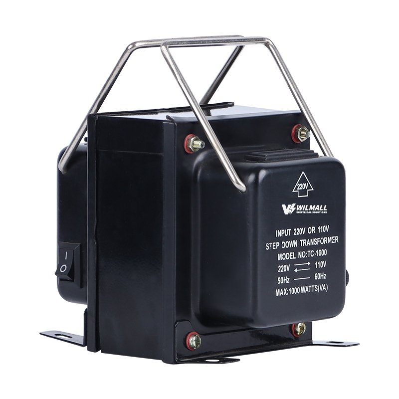
For the control circuit itself we point installers at our TC series control transformers. They are made for exactly this job, small and steady, with a dedicated winding that keeps the control feed clear of the noise elsewhere in the building. The TC-1000 is a common choice on a single passenger lift, and the range covers bigger group controllers as well. If you want to see how these sit alongside our other low-voltage products, the control transformers hub lays it out.
Where the load runs past the control side into car lighting, displays and hoistway lighting, the ST boxes take over. The ST-2000 gives you 2000VA at 220V in and 110V out, and the ST-1500 covers the lighter service circuits. For a group of lifts or a site with mixed 110V and 220V gear, the STU-3000 and STU-5000 run in both directions and carry the heavier duty. The DT-1000VA is the automatic two-way unit for the small, always-on loads that nobody wants to think about.
If a commissioning engineer needs to watch a control voltage settle while setting up an imported controller, the Variac range at 500VA, 1KVA, 2KVA and 3KVA still earns its keep. It is the same family of kit our customers use on other motor-driven jobs, such as the Step Down Transformer for Gate Motor and Garage Door Opener, where a door drive has much in common with a lift door operator.
Minimum Order, Lead Time and Test Records
On the commercial side, our smallest order is 10 pieces, which suits an installer fitting out several shafts or a distributor holding stock. Lead time is 15 to 25 days and depends on the quantity and on any custom labelling or socket requirement. Units ship FOB Ningbo or Shanghai and carry a 12-month warranty.
Each consignment comes with the batch test record, showing the input voltage, the loaded output and the no-load current for the run your units came from. On a lift project that sheet is useful evidence, because the person signing off the installation often wants it. Every unit is wound with copper and tested 100 percent in our own factory in Yueqing before it is packed.
Tell us the cabinet model and the control voltage the controller expects, and we will match the output and the socket at the factory. For a multi-shaft project, we can pack per shaft so the installer is not separating units on site.
What to Send Us About a Lift Supply
You do not need a finished drawing to get a straight answer. Send the lift brand and the controller model if you have them, the number of cars, the mains voltage at the building, and a note of what the control circuit expects. If you have a cabinet schedule, a photo of it is enough for me to read.
It also helps to know the drive type and how the control feed is protected today, so I can tell you whether the arrangement you have in mind is the one we would build. And if the building is still at the design stage, say so. Sizing for the group you plan to end up with is cheaper than adding a second box after the second car arrives.
There are more application guides on the site if you want to compare how we handle other control and motor loads. The themes repeat across sectors, but a lift is the one place where the control feed simply cannot be allowed to drop, and that shapes every choice on this page.
If any part of the cabinet is unclear, send a photo with the enquiry. Supplying a step down transformer for elevator control circuits is something we do regularly, and a short exchange now beats a problem in a shaft that has to be cleared before the inspection.
Lift and Elevator Transformer Questions Installers Ask
These are the ones that reach me most often from lift contractors and maintenance teams, answered as I would on a site call.
How do I size a transformer for an elevator control circuit?
Add the control cabinet, door operators, car lighting and intercom, then allow 30 percent margin. A passenger lift control chain often lands near 1.5kVA, so a 2000VA step down transformer for elevator control work is comfortable. Send us the cabinet schedule and we will confirm it.
Can the control circuit share a supply with the VFD?
I would not share it. The variable-frequency drive on the main motor puts harmonic current back on the supply, and the control sensors that watch the landing should not see it. Give the control circuit its own feed and its own transformer so the drive noise stays on the drive side.
Should an elevator control transformer have an RCD?
Usually not on the safety chain. The safety circuit is designed to stay energised, and a unit that trips on a small leakage current takes the lift out of service for no reason. We build the control feed without a built-in RCD and let the lift engineer specify the protection.
Where should the transformer be installed on a lift?
In the machine room, close to the control cabinet, on a bracket clear of the drive, brake dust and oil spray. Leave air around it and keep it off the pit floor where water gathers. Label every circuit and keep the schedule inside the cabinet door for the next engineer.
Why does the lift control circuit need 110V at all?
Because the controllers, relays, door operators and sensors are built in factories where 110V is the control standard. A lower control voltage is also safer for the technician working with the panel open. The transformer bridges the building supply and that 110V control standard.
Give us the lift details and we will match the control transformer to the cabinet. Send the lift brand, the controller model, the number of cars and the mains voltage at the building. We will come back with a unit and a quantity, and where a group is planned we will size for the shafts you intend to add.
Reach a person directly: WhatsApp +86 197 3022 6757 · Email sales@wilmall.com
MOQ 10 pcs · Lead time 15-25 days · FOB Ningbo or Shanghai · 12-month warranty